All phono cartridges, whether moving magnet (MM) or moving coil (MC) types, generate a signal voltage due to the relative movement of a coil of wire and a magnetic field. In the
MM type the coil of wire is held stationary while the stylus/cantilever assembly is magnetised by small stationary magnets to provide a magnetic field. The varying magnetic field
produced by the moving cantilever produces a small electric current in the coil.
In the MC cartridge, the magnet is stationary while the a small coil is attached to the the
cantilever/stylus assembly. MC coils are considerably smaller than the MM coils and therefore generate a fraction of the output signal voltage. A typical MC cartridge would generate
around 20-100uV as compared to 1-2mV for the same recorded signal with a MM cartridge. The differential equation that describes the signal voltage generated is given by
Faraday's Law:
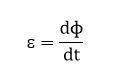
Where  is the signal voltage,
  is the magnetic flux and t is time.
Faraday's Law states that the signal voltage is proportional to the rate of change of the magnetic flux with respect to time.
The displacement from the equilibrium position of the cantilever assembly and the magnetic flux density should be designed to have as close as possible a linear relationaship.
This will ensure that the signal voltage will be proportional to the time rate of change of the position of the stylus. The time rate of change of the position of the cantilever
assembly is actually it's velocity. The waveform recorded in the grooves of a record is not the actual acoustic waveform but its integral with respect to time. If a square wave
is to be reproduced from a record groove, then the recorded waveform in the record groove, will be a triangle waveform - it's time integral.
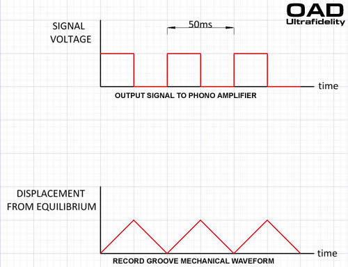
A 20Hz square wave consists of 25ms of constant voltage followed by 25ms of zero voltage. To produce a constant voltage for 25ms, the stylus must move at a constant velocity for 25ms.
If a MM cartridge say produces 1mV/cm/s then to produce a 10mV square wave, the recorded velocity must be 10cm/s. The total distance the cartridge will travel is 25ms x 10cm/s = 2.5mm.
For a 20kHz square wave signal voltage with the same amplitude as the 20Hz signal above, the stylus traces a triangle wave in the groove. However, this time only for 25us. The stlus moves a total
distance of 2.5um. Such small displacements at high frequencies mean that the surface irregulities of the vinyl are increasingly significant and produce a poor signal to noise ratio.
To overcome these problems at both the low frequency and high frequency ends of the audio spectrum, a record is cut by reducing the low frequencies to reduce the stylus displacement and
boosting the high frequencies to improve the signal to noise ratio to acceptable levels.
In order to do this, the frequency response of the recording amplifier is modified to conform to an RIAA (Recording Institute Association of America) equalisation.
Conversely, a phono preamplifier, for both MM and MC, is required to correct for this equalization so that a flat frequency response is heard from 20Hz to 20kHz.
To do this an RIAA correction is incorporated into a phono ampiifier.
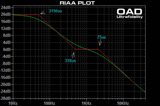
Whilst there are some minor variations, all RIAA phono amplifiers utlize the use of 3 single pole filters.
These filters are:
low pass = 3150us
high pass = 318us
low pass = 75us
Correctly implemented, the overall effect of the 3 filters is shown in the following amplitude vs frequency plot.
A phono amplifier to perform correctly must have the response shown by the green plot line.