MSRP$3136 Click here to buy UP1 Phono Amplifer

The UP1, is a direct coupled low noise amplification design, capable of faithfully reproducing vinyl recordings in a way that has never before been available at this price point. MC/MM input stages are optimized for current noise and voltage noise respectively. Due to this ultra-low noise design, we do not know of any other unit which has an amplification selection of 80dB.
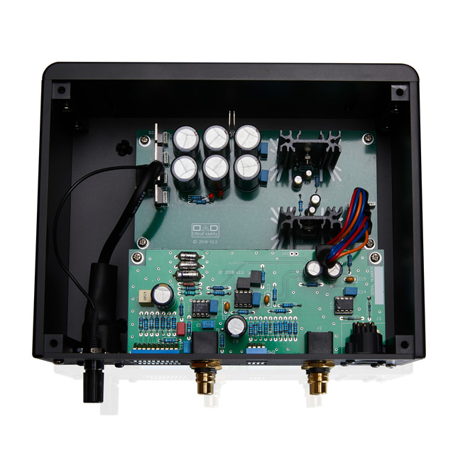
The minimal yet elegant design measuring 210mm wide by 95mm high by 183mm deep the UP1 sports an anodised fully CNC machined chassis that weighs 2.3kg with a separate power supply. Both the Phono chassis and PSU are fitted with anti-vibration feet.
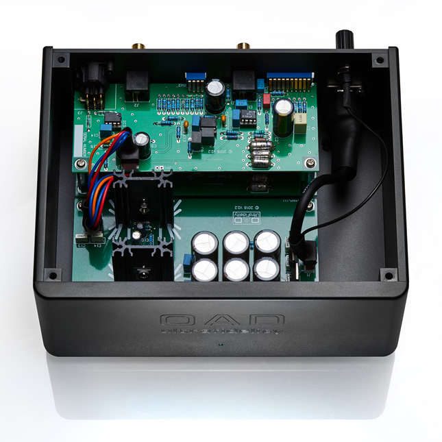
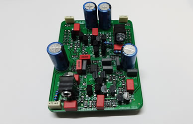
The shielded toroidal transformer is housed in a separate steel chassis to remove any possibilty of compromising noise induced into the phono amplifier. Completely separate circuit boards are implemented for left and right audio channels, with a shared ultra-low noise regulated power supply that comprises 30,000uF of capacitance.
The UP1 is equipped with one set of RCA input jacks and two pairs of output jacks. Both single ended and balanced outputs are catered for.
Each channel has two banks of DIP switches.
One bank provides for: a large selection of input impedance values - 22, 30, 50, 100, 200, 430, 1k and 47k Ohms; additional capacitance; and Moving Magnet/Moving Coil selection. The second bank of
switches sets the overall gain for your cartridge from 40db to 80dB in 5 dB steps. There is no cartridge that the UP1 will not be compatible with.
All phono cartridges, whether moving magnet (MM) or moving coil (MC) types, generate a signal voltage due to the relative movement of a coil of wire and a magnetic field. In the
MM type the coil of wire is held stationary while the stylus/cantilever assembly is magnetised by small stationary magnets to provide a magnetic field. The varying magnetic field
produced by the moving cantilever produces a small electric current in the coil.
In the MC cartridge, the magnet is stationary while the a small coil is attached to the the
cantilever/stylus assembly. MC coils are considerably smaller than the MM coils and therefore generate a fraction of the output signal voltage. A typical MC cartridge would generate
around 20-100uV as compared to 1-2mV for the same recorded signal with a MM cartridge. The differential equation that describes the signal voltage generated is given by
Faraday's Law:
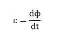
Where  is the signal voltage,
  is the magnetic flux and t is time.
Faraday's Law states that the signal voltage is proportional to the rate of change of the magnetic flux with respect to time.
The displacement from the equilibrium position of the cantilever assembly and the magnetic flux density should be designed to have as close as possible a linear relationaship.
This will ensure that the signal voltage will be proportional to the time rate of change of the position of the stylus. The time rate of change of the position of the cantilever
assembly is actually it's velocity. The waveform recorded in the grooves of a record is not the actual acoustic waveform but its integral with respect to time. If a square wave
is to be reproduced from a record groove, then the recorded waveform in the record groove, will be a triangle waveform - it's time integral.
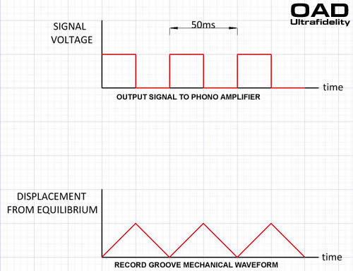
A 20Hz square wave consists of 25ms of constant voltage followed by 25ms of zero voltage. To produce a constant voltage for 25ms, the stylus must move at a constant velocity for 25ms.
If a MM cartridge say produces 1mV/cm/s then to produce a 10mV square wave, the recorded velocity must be 10cm/s. The total distance the cartridge will travel is 25ms x 10cm/s = 2.5mm.
For a 20kHz square wave signal voltage with the same amplitude as the 20Hz signal above, the stylus traces a triangle wave in the groove. However, this time only for 25us. The stlus moves a total
distance of 2.5um. Such small displacements at high frequencies mean that the surface irregulities of the vinyl are increasingly significant and produce a poor signal to noise ratio.
To overcome these problems at both the low frequency and high frequency ends of the audio spectrum, a record is cut by reducing the low frequencies to reduce the stylus displacement and
boosting the high frequencies to improve the signal to noise ratio to acceptable levels.
In order to do this, the frequency response of the recording amplifier is modified to conform to an RIAA (Recording Institute Association of America) equalisation.
Conversely, a phono preamplifier, for both MM and MC, is required to correct for this equalization so that a flat frequency response is heard from 20Hz to 20kHz.
To do this an RIAA correction is incorporated into a phono ampiifier.
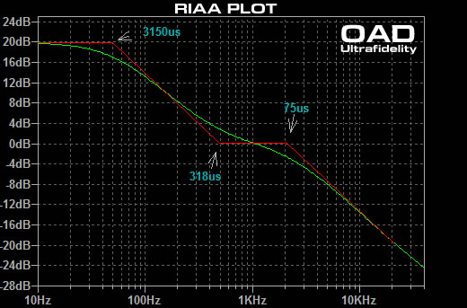
Whilst there are some minor variations, all RIAA phono amplifiers utlize the use of 3 single pole filters.
These filters are:
low pass = 3150us
high pass = 318us
low pass = 75us
Correctly implemented, the overall effect of the 3 filters is shown in the following amplitude vs frequency plot.
A phono amplifier to perform correctly must have the response shown by the green plot line.
Input: RCA
Output: 1 pair Unbalanced RCA (single ended) , 1 pair Balanced XLR
Input impedance:22 Ohm – 47 kOhm (selectable in 8 steps)
Output impedance: 50 ohm
Input capacitance (without additional switched capacitance): 100 pF
Input sensitivity: 200uV – 20 mV
Gain: 40 – 80 dB (2 VRMS output at 1 kHz)
THD 0.005 % (1 kHz)
MM cartridge: >107 dB A-weighted, input shorted
MC cartridge: > 85 dB A-weighted, input shorted
RIAA linearity: +/- 0.2 dB (20 Hz – 20 kHz)
Nominal output: 2 VRMS
Maximum output: 10.5 VRMS
Power consumption: 5 W
Dimensions: Preamplifier W 210 x D 183 x H 95 mm, 2.3 kg
Power Supply: W 114 x D 130 x H 63 mm, 1.25 kg
Shipping Weight: 5kg
MSRP$5799 Click to buy UP1 Reference Phono Amplifier
The UP1 Reference, builds upon the already excellent sound and specifications of the UP1. Essentially, a heavier chassis sports an additional 5 power supplies have been added to further remove any power supply noise from the signal and burying that noise well below what can be heard by the human ear and below the capabilities of the best Test and Measurement equipment. Solid Polymer capacitors have replaced Panasonic low ESR (Equivalent Series Resistance) types in critical areas for unsurpassed audio performance. These capacitors have a higher ripple current, significantly lower ESR, stable capacitance at any temperature and they have no dryout time for greater life.
Each channel has two banks of DIP switches.
One bank provides for: a large selection of input impedance values - 22, 30, 50, 100, 200, 430, 1k and 47k Ohms; additional capacitance; and Moving Magnet/Moving Iron/Moving Coil selection. The second bank of
switches sets the overall gain for your cartridge from 40db to 80dB in 5 dB steps. There is no cartridge that the UP1 Reference will not be compatible with.
All phono cartridges, whether moving magnet (MM) or moving coil (MC) types, generate a signal voltage due to the relative movement of a coil of wire and a magnetic field. In the
MM type the coil of wire is held stationary while the stylus/cantilever assembly is magnetised by small stationary magnets to provide a magnetic field. The varying magnetic field
produced by the moving cantilever produces a small electric current in the coil.
In the MC cartridge, the magnet is stationary while the a small coil is attached to the the
cantilever/stylus assembly. MC coils are considerably smaller than the MM coils and therefore generate a fraction of the output signal voltage. A typical MC cartridge would generate
around 20-100uV as compared to 1-2mV for the same recorded signal with a MM cartridge. The differential equation that describes the signal voltage generated is given by
Faraday's Law:
Where is the signal voltage, is the magnetic flux and t is time.
Faraday's Law states that the signal voltage is proportional to the rate of change of the magnetic flux with respect to time.
The displacement from the equilibrium position of the cantilever assembly and the magnetic flux density should be designed to have as close as possible a linear relationaship.
This will ensure that the signal voltage will be proportional to the time rate of change of the position of the stylus. The time rate of change of the position of the cantilever
assembly is actually it's velocity. The waveform recorded in the grooves of a record is not the actual acoustic waveform but its integral with respect to time. If a square wave
is to be reproduced from a record groove, then the recorded waveform in the record groove, will be a triangle waveform - it's time integral.
A 20Hz square wave consists of 25ms of constant voltage followed by 25ms of zero voltage. To produce a constant voltage for 25ms, the stylus must move at a constant velocity for 25ms.
If a MM cartridge say produces 1mV/cm/s then to produce a 10mV square wave, the recorded velocity must be 10cm/s. The total distance the cartridge will travel is 25ms x 10cm/s = 2.5mm.
For a 20kHz square wave signal voltage with the same amplitude as the 20Hz signal above, the stylus traces a triangle wave in the groove. However, this time only for 25us. The stlus moves a total
distance of 2.5um. Such small displacements at high frequencies mean that the surface irregulities of the vinyl are increasingly significant and produce a poor signal to noise ratio.
To overcome these problems at both the low frequency and high frequency ends of the audio spectrum, a record is cut by reducing the low frequencies to reduce the stylus displacement and
boosting the high frequencies to improve the signal to noise ratio to acceptable levels.
In order to do this, the frequency response of the recording amplifier is modified to conform to an RIAA (Recording Institute Association of America) equalisation.
Conversely, a phono preamplifier, for both MM and MC, is required to correct for this equalization so that a flat frequency response is heard from 20Hz to 20kHz.
To do this an RIAA correction is incorporated into a phono ampiifier.
Whilst there are some minor variations, all RIAA phono amplifiers utlize the use of 3 single pole filters.
These filters are:
low pass = 3150us
high pass = 318us
low pass = 75us
Correctly implemented, the overall effect of the 3 filters is shown in the following amplitude vs frequency plot.
A phono amplifier to perform correctly must have the response shown by the green plot line.
Input: RCA
Output: 1 pair Unbalanced RCA (single ended) , 1 pair Balanced XLR
Input impedance:22 Ohm,30 Ohms, 50 Ohms, 100 Ohms, 220 Ohms, 470 ohms, 1000 Ohms, 47k Ohms
Output impedance: 50 ohm
Input capacitance (without additional switched capacitance): 100 pF
Input sensitivity: 200uV – 20 mV
Gain: 40 – 80 dB (2 VRMS output at 1 kHz)
THD 0.004 % (1 kHz)
MM cartridge: >113 dB A-weighted, input shorted
MC cartridge: > 93 dB A-weighted, input shorted
RIAA linearity: +/- 0.1 dB (20 Hz – 20 kHz)
Nominal output: 2 VRMS
Maximum output: 10.5 VRMS
Power consumption: 5 W
Dimensions: Preamplifier W 210 x D 183 x H 95 mm, 3.3 kg
Power Supply: W 114 x D 130 x H 63 mm, 1.25 kg
Shipping Weight: 6kg
The preamplifier remains the central control unit, the real heart of the hi-fi system. The preamplifier is irreplaceable for sonic reasons.
The Padma sports a fully CNC remote control and chassis of premium grade aluminium, ensuring an inert and stable base. Available in silver or black, its robust and sophisticated design ensures an efficient assembly and timeless appearance around an innovative design.
Since the release of the CP1 six years ago (2016) the entire wealth of OAD's experience was utilized to develop the new Padma Preamplifier. The Padma represents an uncompromising harmony of technology, styling and functionality, boasting ultimate performance and sound quality that ushers in a new era of the preamplifier.
In the CP1, the all discrete line stage which elevated single ended circuits to an unparalled level is further elevated by driving two such units in parallel, resulting in the Dual Balanced Topology which significantly improves electrical and sonic characteristics. Compared to the CP1 model, the already excellent noise level is reduced by a further 30 percent.
Volume knob mechanism by OAD Ultrafidelity
The volume has an attenuation range of 73 steps, 0.5dB per step. Balance range is +/-6dB (double the volume) in precisely 0.5dB steps. The volume control uses laser cut precision, lowest-noise and zero-induction resistors on a single die that have a zero temperature coefficient. Hence there is no possibility of change in resistance. The attenuator has a constant output impedance and extremely low Johnson noise that is consistent across all volume settings. Potentiometers and stepped attenuators cannot give superior right to left volume level matching that is critical when listening. Potentiometer based volume controls, such as even the best (Alps Blue Velvet) typically have something like +/-20% tolerance so the left to right channel matching can easily be out by as much as 2dB. The output impedance of such volume controls (and associated Johnson noise) also varies by where the volume control is set. For example, a 50K ohm volume control set to the middle will have 15 times or 23dB the noise of the Padma volume control. The Padma is immune to influences like mains quality and the choice of interconnects. The volume control directly controls the gain of the output stage via a digital link. This digital link allows the volume circuitry to be placed as close as possible to the input and output connectors to minimze the signal path for optimal purity. Accuracy, linearity and dynamic range of this arrangement is much greater than those of stepped attenuators and potentiometers. Operation is smooth and glitch free.
The entire path for all signals from the input connectors to the outputs is fully balanced. Audio purity is maximised by using minimal components in the signal path. Moreover, crosstalk is virtually eliminated by using a dual mono layout for left and right channels. Once again, only low-noise and zero-induction resistors are used.
Experience the ideal image for music playback that the Padma delivers. The music echoes throughout a space surrounded by silence.
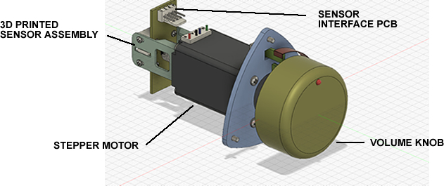
The music signal does not pass through the volume sensor mechanism. It is just a position sensor to be able to set the desired volume. However, the look and feel of the volume knob is very important to audiophiles. A stepper motor delivers an elegant solution to volume control whilst still maintaining the timeless appearance and feel of a traditional knob.
Line Level Inputs: 3 Balanced and 6 Unbalanced
Line Level Outputs: 1 Balanced and 1 Unbalanced, 1 Balanced and 1 Unbalanced Home Theatre outputs
Overall Gain (dB): -63 to 9.7
Frequency Response (kHz): 0 - 650 -3dB @ 1.8VRMS Output
Maximum Output: >20V RMS
Signal to Noise Ratio (dB): >110dB A-weighted input shorted
Weight: 13 kg (28.7 lbs)
Shipping Weight: 14.6 kg (32.2 lbs)
Dimensions (WxHxD mm): 438 x 126 x 353 (17.2” x 4.96” x 13.9”)
Shipping Dimensions (HxWxD mm): 235 x 570 x 500 (9.3” x 22.5” x 19.7”)
The Vajra Class AB precision stereo power amplifier provides supreme driving performance. The Vajra will bring out the very best of any speaker, allowing you to enjoy never-before experienced soundscapes.
The Vajra, like the Padma, sports a fully CNC chassis of premium grade aluminium, ensuring an inert and stable base. Available in silver or black, its robust and sophisticated design ensures an efficient assembly and timeless appearance around an innovative design.
The Vajra uses the highest quality components available. Each component is tested for it's linearity. Linearity is a test of a component's input to output relationship. Only components with perfect linearity are used to ensure the highest accuracy and musicality.
Download Vajra User Manual: OAD Vajra Owner's Manual
Frequency Response (Hz) -3dB 0-100k
Power @ 8 Ohms 240VAC (W) 180
Power @ 4 Ohms 240VAC (W) 360
Gain (dB) 27
Sensitivity 4 V (BAL) 2 V (SE)
Input Impedance (Ohms) 24K (BAL) 12K (SE)
Damping factor >500
Noise Out <-100dBu(0-22kHz, Rs=50R)
THD 0.001% at 1kHz (100kHz Bandwidth)
Dimensions (WxHxD mm): 430 x 160 x 360
OAD Ultrafidelity Pty Ltd, was founded in 2015 by Jon De Sensi. Operating out of his workshop at home, development of unique design prototypes of a fully discrete Class A preamplifier
and Class AB power amplifier.
The first products shipped were the CP1 preamplifier and the UF1 power amplifier. The CP1 utilized a touch screen and a full function remote control. The touch screen allowed for
digital control at the front end of the ampliifer, whilst the R2R ladder attenuator volume control was placed right behind the incoming phono sockets for shortest signal path.
A rare discrete shunt voltage regulator was used for the low constant output impedance and complete immunity to any incoming power supply noise.
The UF1 used a rare output stage arrangement for better linearity than the ubiqutous emitter/source follower output stage. ThermalTrak transistors meant Class A distortion figures were
achieved but with Class AB dynamics. These products were distributed in Australia by the Pure Music Group, one of the most presitgious hi-end importers in Australia. Today, their retail store,
Sonic Purity, continues to sell the UP1 phono amplifier, which was designed in conjunction to pair with their excellent range of turntables, such as Kuzma, SME and TechDAS to name a few.
Years later these products matured to the current Padma preamp and Vajra power amplifier. These new amplifiers sport fully CNC machined chassis.
The Padma preamp has 4 discrete lines stages for a full true balanced design, from input to output.
The Vajra power amplifier was (and still may be) the first amplifier to use slit foil capacitors to eliminate circulating eddy currents in the outer foil that would otherwise smear
sound from the lower midrange frequencies and up. It continues to use the rare Complimentary Feedback output design.
Jon De Sensi, the designer of all OAD Ultrafidelity products - dipole speakers, phono amps, preamps, power amplifiers and a DAC/Streamer is no newcomer to the hi-end industry.
In 1990, he started Music Labs whilst working for the Department of Defence as a civilian engineer and later re-designed parts of Australia's weather radar by replacing, by then, the
unreliable vacuum tube designs with solid state designs for superior performance. Music Labs manufactured one of the best and technologically advanced DACs the world had seen at the time.
Preampliifers and Power Ampliifiers with unique designs were also part of the line up.
The following are links to just some of the reviews received in the 1990's.